Underwater ROV Telemetry: Hardware, Firmware, and a Protocol Audit
A degree-project archive brings together custom acquisition boards, embedded firmware and a modern audit of the serial protocol.
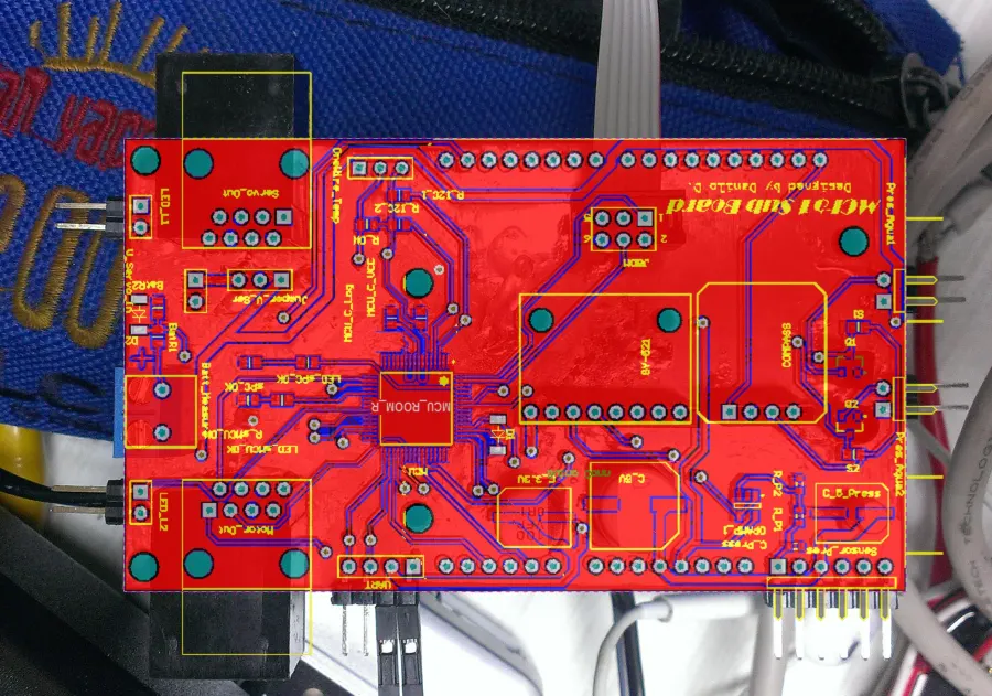
Vector rendering of the 2-layer acquisition PCB designed by Danilo Díaz Tarascó for the X-Sub underwater robot. The board measures 93.1 by 53.9 millimeters and has 46 footprints, 39 named nets, 457 copper track segments and 33 vias around a Freescale MCF51QE128CLH microcontroller.
Trace a signal
Select a signal group to trace its real copper tracks, vias, and pads on the board.
| MCU | MCF51QE128CLH |
|---|---|
| Board | 93.1 × 53.9 mm |
| Copper layers | 2 |
| Footprints | 46 |
| Named nets | 39 |
| Track segments | 457 |
| Vias | 33 |
Trace a signal
- IMU & compass
- I²C bus reading 6-axis motion from the MPU-6050 and heading from the HMC6352 digital compass.
- Thrusters ×4
- Four PWM channels driving bidirectional brushless ESCs for underwater propulsion and maneuvering.
- Depth sensor
- Scales the MPX5700AP pressure sensor via an OPA345 op-amp to measure dive depth at the 3.3 V ADC.
- Water ingress
- Two digital probes inside the sealed housing that alert the controller if water enters the hull.
- Camera pan/tilt
- Two PWM servo lines that pan and tilt the underwater inspection camera from surface commands.
- Serial link
- UART link carrying 27-byte telemetry frames and 10-byte commands between the MCU and onboard pcDuino.
- LED lights
- Two transistor-switched PWM outputs dimming high-intensity LED lamps for underwater visibility.
- Battery monitor
- Resistive voltage divider feeding pack voltage into ADC channel 5 to track remaining dive power.
- Power rails
- The PCB routes 3.3 V logic, 5 V sensors and servo power separately, with a common ground.
The problem
An underwater remotely operated vehicle (ROV) concentrates every boundary problem found in industrial IoT inside a sealed pressure housing. Sensors on different electrical buses must be sampled reliably, actuator commands must reach thrusters and lighting without jitter, power distribution has to survive inductive motor loads, and a single serial link between the embedded controller and the onboard computer has to carry both telemetry and teleoperation frames cleanly.
Between 2015 and 2016, I designed and validated the telemetry and teleoperation system for X-Sub, an underwater robot developed by the Mechatronics Research and Development Group at Universidad Simón Bolívar. The work earned an honorific mention as my undergraduate Electronics Engineering thesis (the full 137-page Spanish thesis is preserved in Libro Tesis.pdf). Years later, rather than leaving the project as an opaque archive of legacy binaries, I audited the original firmware and hardware files and added modern, dependency-free verification tooling so any engineer can inspect the design honestly.
System architecture
The archived vehicle architecture splits real-time sensing and actuation from higher-level logging and surface visualization:
- Embedded controller (
MCU Firmware/X-Sub MCU Firmware/): A 32-bit Freescale MCF51QE128 (ColdFire V1) microcontroller developed in CodeWarrior with Processor Expert drivers and custom C logic inxSub.c,OneWire.c, andmain.c. - Sensor interfaces: An MPU-6050 inertial measurement unit and HMC6352 digital compass over I²C; a DS18B20 external temperature sensor over 1-Wire; an MPX5700AP pressure sensor and battery-voltage monitoring over ADC; and digital water-presence inputs over GPIO.
- Actuator outputs: PWM channels driving four bidirectional brushless ESCs, two pan/tilt camera servos, and two high-intensity LED loads, alongside status and handshake indicators.
- Custom PCBs (
PCB/): Two Altium Designer boards —X-Sub_Boardfor acquisition, control, and sensor interfaces, andpcDuino Link Boardfor power distribution and controller-to-computer interconnection. - Onboard and surface path: The MCF51QE128 exchanges fixed-length binary frames over UART (115200 baud in the Python experiments) with an onboard pcDuino, which relays telemetry to surface logging and visualization prototypes originally explored in Python 3.4, LabVIEW, and MATLAB/Simulink.
Auditing the wire protocol
Re-examining the C source (xSub.c, Events.c, Init.c) a decade later shows both what worked and what would fail a modern production review:
- Telemetry frames (27 bytes): Big-endian 16-bit readings covering status, external and internal temperature, external pressure, 3-axis acceleration, 3-axis angular velocity, linear velocity, compass heading, water-presence state, and battery level, ending with a
0xFFterminator. - Command frames (10 bytes): Four motor setpoints, camera pan and tilt, two light channels, a PC status byte (each 0–255), and a
0xFFterminator. - Documented failure modes: Although byte 25 of the telemetry frame is named
XORin the archived firmware, initialization assigns the fixed decimal constant26and no checksum calculation runs during frame assembly. Likewise, the protocol has no framing escape or resynchronization mechanism, no sequence numbers, no command timeout encoded on the wire, and no authentication.
In docs/PROTOCOL.md and docs/HARDWARE.md, those gaps are documented explicitly instead of glossed over. Any production telemetry link for industrial hardware needs a real CRC, deterministic framing (such as COBS or length-prefixed frames), watchdog fail-safes on command loss, and replay/authentication controls whenever commands cross an untrusted network.
Modern verification boundary
Legacy CodeWarrior, LabVIEW, and MATLAB binary projects cannot safely be assumed to compile or run unchanged ten years later. The maintained boundary of the repository is therefore deliberately narrow and verifiable:
tools/xsub_protocol.pyprovides a dependency-free Python 3.11+ CLI to decode 27-byte telemetry frames (reporting raw unsigned integers and offering two's-complement conversion viasigned_16()without fabricating sensor calibration curves) and encode 10-byte command frames for inspection.- Automated CI (
quality.ymlandcodeql.yml) runs Ruff linting, unit tests, andscripts/verify_repository.pyto validate artifact hashes and repository hygiene, whiledocs/HARDWARE.mdlays out a seven-step electrical, DRC/ERC, current-limited bring-up, and recalibration checklist before anyone powers an archived board.
Takeaway
Good embedded engineering is as much about knowing where a design stops being safe as making it work on the bench. Preserving X-Sub/Telemetry-System with an honest protocol audit, explicit safety warnings, and automated verification demonstrates the exact review lens I bring to connected hardware projects today.